Hello everyone
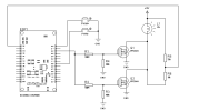
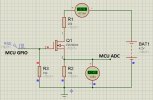
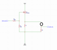
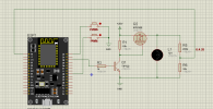
I need technical help on how I can measure the voltage using the ESP8266 ADC and using a FET N. In this way, the ADC is reading 12V directly. I think there is another solution, but I'm stuck on this. If anyone has a tip on how to read the voltage correctly, I'll be happy.
I need technical help on how I can measure the voltage using the ESP8266 ADC and using a FET N. In this way, the ADC is reading 12V directly. I think there is another solution, but I'm stuck on this. If anyone has a tip on how to read the voltage correctly, I'll be happy.