B4R Library rSPI

Hi all,

yesterday I was watching a tutorial about using spi library in Arduino. I tried to port this in B4R. I think I succeeded but someone more experienced should check it and let me know if everything works ok. There is the necessary needed functionality in the Code Module but there are also some additions. Please check and let me know if everything is ok.

Please take under note that (as described in this tutorial) not all boards support the begin transaction command (that this library uses):


and you must check it.

Further more you must be aware that this impementation transfers a byte and receives a byte and if your device communication implementation (protocol) requires multiple bytes transfer (as it is mentioned in several online videos) it will not work. Be aware also that you must know the frequency of communications (MAX = 20000000) and also if it is MSBFIRST or LSBFIRST and at last the SPI_MODEx where x=0,1,2,3 in order to make it work.

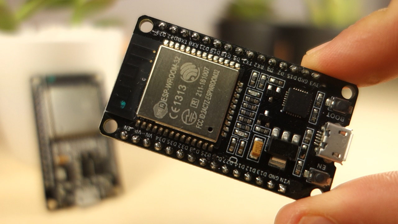
See the attached example. Feel free to post corrections. Please note that until today (25/10/2021) the library works only for Arduino and ESP8266.

(21-9-2021)
Four new functions have been added:

B4X:
'This command will write to the logs "--" if the board is not supported
'and "-You can use this library with your board-" if your board is supported
SPI.CheckIfThisBoardIsSupported

'Transfer Byte Array
Dim iDimension As UInt = 3
Dim bSend(iDimension) As Byte
bSend(0) = SPI.GetByteFromString("11001100")
bSend(1) = SPI.GetByteFromString("01100110")
bSend(2) = SPI.GetByteFromString("00110011")
Dim bRet(iDimension) As Byte
SPI.Transfer_Byte_Array(bSend, bRet)
 
'Disable Inerrupts
SPI.DisableInterrupts

'Enable Inerrupts
SPI.EnableInterrupts


(3-2-2021) Two new functions have been added:

B4X:
    Dim b as Byte
    b = SPI.Transfer_Byte(SPI.GetByteFromString("01100111"))

    'We are interested only in the last 4 bits
    b = SPI.ApplyMask(b, SPI.GetByteFromString("00001111"))
    Log(b)

    'We want to know the value of the 2nd bit from right in the byte
    Dim iBitInSecondPositionFromRight As UInt = SPI.GetBitAt(b, 2)
    Log(iBitInSecondPositionFromRight)
 

Attachments

  • rSPI.b4xlib
    1.6 KB · Views: 375
  • SPI.zip
    2.6 KB · Views: 372
Last edited:

hatzisn

Expert
Licensed User
Longtime User
(3-2-2021) Two new functions have been added:

B4X:
    Dim b as Byte
    b = SPI.Transfer_Byte(SPI.GetByteFromString("01100111"))

    'We are interested only in the last 4 bits
    b = SPI.ApplyMask(b, SPI.GetByteFromString("00001111"))
    Log(b)

    'We want to know the value of the 2nd bit from right in the byte
    Dim iBitInSecondPositionFromRight As UInt = SPI.GetBitAt(b, 2)
    Log(iBitInSecondPositionFromRight)
 
Last edited:

lenk54

Member
Licensed User
Longtime User
Hi all,

yesterday I was watching a tutorial about using spi library in Arduino. I tried to port this in B4R. I think I succeeded but someone more experienced should check it and let me know if everything works ok. There is the necessary needed functionality in the Code Module but there are also some additions. Please check and let me know if everything is ok.

See the attached example. Feel free to post corrections.
Hi

I am trying to connect Arduino Nano to a MAX31856 which is a thermocouple chip. It uses SPI to communicate.
I have tried different MODES and different delays between each operation but cannot communicate.

I would eventually like to port it to ESP8266/ESP32. (I think the pins for ESP32 CS/SS (5), MOSI (23), MISO (19), CLK (18)?)
To communicate with MAX31856 MSBFIRST:-
Set CS/SS low SPI.CSPinActivate(CSPin)
Send address byteSPI.Transfer_Byte(0x0C ))
Read byte/bytes or (Send Configuration byte/s) a = SPI.Transfer_Byte(10)]
Set CS/SS high SPI.CSPinDeActivate(CSPin)

I have been able to communicate using a different BASIC using the same logic and it works. (I use B4J and B4A as part of the project so I would like to use B4R.)

Am I using the correct CS/SS (10), MOSI (11), MISO (12), CLK (13)? Can they be changed?

Also Adafruit has a library (Adafruit_MAX31856.h) which I have tried using Arduino IDE and works fine with Arduino but not ESP8266/ESP32.

Any help would be appreciated.
 

hatzisn

Expert
Licensed User
Longtime User

Have you tried in the AppStart to set before try to communicate with it:

B4X:
SPI.CSPinDeActivate(CSPin)


It might also be that you need to send a bunch of bytes (buffer) as described in the SPI library in Arduino site but I have not added this. I will add it a.s.a.p.
You may also try to debug it by logging the response byte and check if it is what you expected.
 
Last edited:

hatzisn

Expert
Licensed User
Longtime User

hatzisn

Expert
Licensed User
Longtime User
Hi

I am trying to connect Arduino Nano to a MAX31856 which is a thermocouple chip. It uses SPI to communicate.
I have tried different MODES and different delays between each operation but cannot communicate.

I would eventually like to port it to ESP8266/ESP32. (I think the pins for ESP32 CS/SS (5), MOSI (23), MISO (19), CLK (18)?)
To communicate with MAX31856 MSBFIRST:-
Set CS/SS low SPI.CSPinActivate(CSPin)
Send address byteSPI.Transfer_Byte(0x0C ))
Read byte/bytes or (Send Configuration byte/s) a = SPI.Transfer_Byte(10)]
Set CS/SS high SPI.CSPinDeActivate(CSPin)

I have been able to communicate using a different BASIC using the same logic and it works. (I use B4J and B4A as part of the project so I would like to use B4R.)

Am I using the correct CS/SS (10), MOSI (11), MISO (12), CLK (13)? Can they be changed?

Also Adafruit has a library (Adafruit_MAX31856.h) which I have tried using Arduino IDE and works fine with Arduino but not ESP8266/ESP32.

Any help would be appreciated.

Please take also a look at this:


If you take a look at page 2 of the PDF you will see that the maximum for a Pin is 4,3V and arduino nano has 5V logic. There is a good chance you have broken it since you did not mention there is a voltage devider.
 

lenk54

Member
Licensed User
Longtime User
hi

Thanks for the replies.

Please take also a look at this:


If you take a look at page 2 of the PDF you will see that the maximum for a Pin is 4,3V and arduino nano has 5V logic. There is a good chance you have broken it since you did not mention there is a voltage devider.

I am using a purpose breakout board suitable for 5v - as i mentioned the uno works fine with Adafruit_MAX31856.h library.
My version of code:
#Region Project Attributes
    #AutoFlushLogs: True
    #CheckArrayBounds: True
    #StackBufferSize: 300
#End Region
'Ctrl+Click to open the C code folder: ide://run?File=%WINDIR%\System32\explorer.exe&Args=%PROJECT%\Objects\Src

Sub Process_Globals
    Public Serial1 As Serial
    Public CSPin As Pin
    Dim n As Byte
    Dim ab As Byte  'address byte
    ab=0x0C
    Dim hb As Byte  'high byte
    Dim mb As Byte  'mid byte
    Dim lb As Byte  'low byte
End Sub

Private Sub AppStart
    Serial1.Initialize(115200)
    Log("AppStart")
    CSPin.Initialize(10, CSPin.MODE_OUTPUT) 'I am using pin 10 for CS
    SPI.CSPinDeActivate(CSPin)
    'CSPin.DigitalWrite(True)
    
    For n=1 To 255
    CommunicateThroughSPI
    Delay(1000)
    Next
End Sub


Private Sub CommunicateThroughSPI


    Delay(10)
    
    SPI.CSPinActivate(CSPin)
    'CSPin.DigitalWrite(False)
    SPI.Begin_Transaction(2000000, SPI.MSBFIRST, SPI.SPI_MODE0)
    Delay(10)
    SPI.Transfer_Byte(ab)  'Address byte
    Delay(10)
    hb = SPI.Transfer_Byte(0)  'HB      SPI.Transfer_Byte(x)  tried x=0 to x=255
    Delay(10)
    mb = SPI.Transfer_Byte(0)  'MB
    Delay(10)
    lb = SPI.Transfer_Byte(0)  'LB
    Delay(10)
    Log("Returned:")
    Log(hb)
    Log(mb)
    Log(lb)
    'CSPin.DigitalWrite(True)
    SPI.End_Transaction
    SPI.CSPinDeActivate(CSPin)
End Sub

Boards I have tried :-
Arduino uno ) For Arduino boards I stuck with the H/W pins which I know work with other BASICS and Adafruit library
Arduino nano ) SS/CS=10 MOSI=11 MISO=12 CLK=13


Wemos ESP8266 D1 R1 )
Wemos ESP32 D1 R32 )
ESP WROOM 32 ) this board has VSPI & HSPI (TRIED BOTH)
Tried:-
SS/CS =5 MOSI=23 MISO=19 SCK =14
SS/CS =10 MOSI=11 MISO=12 SCK =13
SS/CS =15 MOSI=13 MISO=12 SCK =14
SS/CS =10 MOSI= 7 MISO=6 SCK =3
And many other combinations and also tried different pins for CS - Does CS need to be held low with a pull down resister?

Yes I tried SPI.CSPinDeActivate(CSPin) in appstart. I have also tried setting CS directly CSPin.DigitalWrite(False)/CSPin.DigitalWrite(True)

I need to read 3x bytes the response from the MAX31856 is Send byte 0x0C (register address) returns HB (127) MID(255) LOW (255)

I have tried setting a loop to try different delays with each MODE but MODE change returns 0 .

I have not sent a bunch of bytes but will try.

I am using a purpose built breakout board suitable for 5v - as I mentioned the uno works fine with Adafruit_MAX31856.h library and Arduino IDE. To make sure I have just tried it again, working fine.


Thanks again
 

hatzisn

Expert
Licensed User
Longtime User
hi

Thanks for the replies.


My version of code:
#Region Project Attributes
    #AutoFlushLogs: True
    #CheckArrayBounds: True
    #StackBufferSize: 300
#End Region
'Ctrl+Click to open the C code folder: ide://run?File=%WINDIR%\System32\explorer.exe&Args=%PROJECT%\Objects\Src

Sub Process_Globals
    Public Serial1 As Serial
    Public CSPin As Pin
    Dim n As Byte
    Dim ab As Byte  'address byte
    ab=0x0C
    Dim hb As Byte  'high byte
    Dim mb As Byte  'mid byte
    Dim lb As Byte  'low byte
End Sub

Private Sub AppStart
    Serial1.Initialize(115200)
    Log("AppStart")
    CSPin.Initialize(10, CSPin.MODE_OUTPUT) 'I am using pin 10 for CS
    SPI.CSPinDeActivate(CSPin)
    'CSPin.DigitalWrite(True)
 
    For n=1 To 255
    CommunicateThroughSPI
    Delay(1000)
    Next
End Sub


Private Sub CommunicateThroughSPI


    Delay(10)
 
    SPI.CSPinActivate(CSPin)
    'CSPin.DigitalWrite(False)
    SPI.Begin_Transaction(2000000, SPI.MSBFIRST, SPI.SPI_MODE0)
    Delay(10)
    SPI.Transfer_Byte(ab)  'Address byte
    Delay(10)
    hb = SPI.Transfer_Byte(0)  'HB      SPI.Transfer_Byte(x)  tried x=0 to x=255
    Delay(10)
    mb = SPI.Transfer_Byte(0)  'MB
    Delay(10)
    lb = SPI.Transfer_Byte(0)  'LB
    Delay(10)
    Log("Returned:")
    Log(hb)
    Log(mb)
    Log(lb)
    'CSPin.DigitalWrite(True)
    SPI.End_Transaction
    SPI.CSPinDeActivate(CSPin)
End Sub

Boards I have tried :-
Arduino uno ) For Arduino boards I stuck with the H/W pins which I know work with other BASICS and Adafruit library
Arduino nano ) SS/CS=10 MOSI=11 MISO=12 CLK=13


Wemos ESP8266 D1 R1 )
Wemos ESP32 D1 R32 )
ESP WROOM 32 ) this board has VSPI & HSPI (TRIED BOTH)
Tried:-
SS/CS =5 MOSI=23 MISO=19 SCK =14
SS/CS =10 MOSI=11 MISO=12 SCK =13
SS/CS =15 MOSI=13 MISO=12 SCK =14
SS/CS =10 MOSI= 7 MISO=6 SCK =3
And many other combinations and also tried different pins for CS - Does CS need to be held low with a pull down resister?

Yes I tried SPI.CSPinDeActivate(CSPin) in appstart. I have also tried setting CS directly CSPin.DigitalWrite(False)/CSPin.DigitalWrite(True)

I need to read 3x bytes the response from the MAX31856 is Send byte 0x0C (register address) returns HB (127) MID(255) LOW (255)

I have tried setting a loop to try different delays with each MODE but MODE change returns 0 .

I have not sent a bunch of bytes but will try.

I am using a purpose built breakout board suitable for 5v - as I mentioned the uno works fine with Adafruit_MAX31856.h library and Arduino IDE. To make sure I have just tried it again, working fine.


Thanks again

Can you please provide the code you use that works in the Arduino Environment?


Edit - Also check the clock frequency
 

lenk54

Member
Licensed User
Longtime User
Can you please provide the code you use that works in the Arduino Environment?


Edit - Also check the clock frequency

Arduino code as requested. I think most of the work is done in the library.

Arduino code Adafruit_MAX31856:
// This example demonstrates doing a one-shot measurement "manually".
// Separate calls are made to trigger the conversion and then check
// for conversion complete. While this typically only takes a couple
// 100 milliseconds, that times is made available by separating these
// two steps.

#include <Adafruit_MAX31856.h>

// Use software SPI: CS, DI, DO, CLK
//Adafruit_MAX31856 maxthermo = Adafruit_MAX31856(10, 11, 12, 13);
// use hardware SPI, just pass in the CS pin
Adafruit_MAX31856 maxthermo = Adafruit_MAX31856(10);

void setup() {
  Serial.begin(115200);
  while (!Serial) delay(10);
  Serial.println("MAX31856 thermocouple test");

  if (!maxthermo.begin()) {
    Serial.println("Could not initialize thermocouple.");
    while (1) delay(10);
  }

  maxthermo.setThermocoupleType(MAX31856_TCTYPE_K);

  Serial.print("Thermocouple type: ");
  switch (maxthermo.getThermocoupleType() ) {
    case MAX31856_TCTYPE_B: Serial.println("B Type"); break;
    case MAX31856_TCTYPE_E: Serial.println("E Type"); break;
    case MAX31856_TCTYPE_J: Serial.println("J Type"); break;
    case MAX31856_TCTYPE_K: Serial.println("K Type"); break;
    case MAX31856_TCTYPE_N: Serial.println("N Type"); break;
    case MAX31856_TCTYPE_R: Serial.println("R Type"); break;
    case MAX31856_TCTYPE_S: Serial.println("S Type"); break;
    case MAX31856_TCTYPE_T: Serial.println("T Type"); break;
    case MAX31856_VMODE_G8: Serial.println("Voltage x8 Gain mode"); break;
    case MAX31856_VMODE_G32: Serial.println("Voltage x8 Gain mode"); break;
    default: Serial.println("Unknown"); break;
  }

  maxthermo.setConversionMode(MAX31856_ONESHOT_NOWAIT);
}

void loop() {
  // trigger a conversion, returns immediately
  maxthermo.triggerOneShot();

  //
  // here's where you can do other things
  //
  delay(500); // replace this with whatever
  //
  //

  // check for conversion complete and read temperature
  if (maxthermo.conversionComplete()) {
    Serial.println(maxthermo.readThermocoupleTemperature());
  } else {
    Serial.println("Conversion not complete!");
  }
}
 

hatzisn

Expert
Licensed User
Longtime User
Arduino code as requested. I think most of the work is done in the library.

Arduino code Adafruit_MAX31856:
// This example demonstrates doing a one-shot measurement "manually".
// Separate calls are made to trigger the conversion and then check
// for conversion complete. While this typically only takes a couple
// 100 milliseconds, that times is made available by separating these
// two steps.

#include <Adafruit_MAX31856.h>

// Use software SPI: CS, DI, DO, CLK
//Adafruit_MAX31856 maxthermo = Adafruit_MAX31856(10, 11, 12, 13);
// use hardware SPI, just pass in the CS pin
Adafruit_MAX31856 maxthermo = Adafruit_MAX31856(10);

void setup() {
  Serial.begin(115200);
  while (!Serial) delay(10);
  Serial.println("MAX31856 thermocouple test");

  if (!maxthermo.begin()) {
    Serial.println("Could not initialize thermocouple.");
    while (1) delay(10);
  }

  maxthermo.setThermocoupleType(MAX31856_TCTYPE_K);

  Serial.print("Thermocouple type: ");
  switch (maxthermo.getThermocoupleType() ) {
    case MAX31856_TCTYPE_B: Serial.println("B Type"); break;
    case MAX31856_TCTYPE_E: Serial.println("E Type"); break;
    case MAX31856_TCTYPE_J: Serial.println("J Type"); break;
    case MAX31856_TCTYPE_K: Serial.println("K Type"); break;
    case MAX31856_TCTYPE_N: Serial.println("N Type"); break;
    case MAX31856_TCTYPE_R: Serial.println("R Type"); break;
    case MAX31856_TCTYPE_S: Serial.println("S Type"); break;
    case MAX31856_TCTYPE_T: Serial.println("T Type"); break;
    case MAX31856_VMODE_G8: Serial.println("Voltage x8 Gain mode"); break;
    case MAX31856_VMODE_G32: Serial.println("Voltage x8 Gain mode"); break;
    default: Serial.println("Unknown"); break;
  }

  maxthermo.setConversionMode(MAX31856_ONESHOT_NOWAIT);
}

void loop() {
  // trigger a conversion, returns immediately
  maxthermo.triggerOneShot();

  //
  // here's where you can do other things
  //
  delay(500); // replace this with whatever
  //
  //

  // check for conversion complete and read temperature
  if (maxthermo.conversionComplete()) {
    Serial.println(maxthermo.readThermocoupleTemperature());
  } else {
    Serial.println("Conversion not complete!");
  }
}

Thanks for replying. Indeed the functionality is included in the library. Have you checked to set the correct frequency of the clock for communications (the 2000000 in begin_transaction) ?
 

candide

Active Member
Licensed User
why not to use a library with a wrapper ?
in zip attached, you can find a wrapper for Adafruit_MAX31856 and it should be easy to use it in B4R
 

Attachments

  • rAdafruit_MAX31856.zip
    23.3 KB · Views: 327

hatzisn

Expert
Licensed User
Longtime User
Another possible explanation for the fact that it does not work is the delay the execution of the code its self imposes. Once I was trying to use an HC-SR04+ (3,3V powered and enabled) with a WeMos D1 Mini. It wasn't working because I was logging a message after triggering it and before measuring the pulseIn in inline C. Once I removed the logging it worked perfectly.
 

hatzisn

Expert
Licensed User
Longtime User
why not to use a library with a wrapper ?
in zip attached, you can find a wrapper for Adafruit_MAX31856 and it should be easy to use it in B4R

Thank you @candide for your job. Just an addendum which puzzled me a bit. One needs this library installed in Arduino IDE in order for your library to work.

1613549981422.png


I do not have a MAX31856 thermocoupler but at least with this library it compiles ok.

Please add your library to the B4R libraries forum.
 
Last edited:

lenk54

Member
Licensed User
Longtime User
Hi

Thanks candide and hatzisn for your help, I really appreciate the work you have done.
I have tried the wrapped library with a uno and it seems to work great. I now need to work out which pins I need to connect to the Wemos d1 r1 and also the WROOM 32.

If you have any pointers I would appreciate it.

Thanks again.
 

candide

Active Member
Licensed User
with google you can find some answers :
for wemos d1 r1 :
#define D0 16
#define D1 5 // I2C Bus SCL (clock)
#define D2 4 // I2C Bus SDA (data)
#define D3 0
#define D4 2 // Same as “LED_BUILTIN”, but inverted logic
#define D5 14 // SPI Bus SCK (clock)
#define D6 12 // SPI Bus MISO
#define D7 13 // SPI Bus MOSI
#define D8 15 // SPI Bus SS (CS)
#define D9 3 // RX0 (Serial console)
#define D10 1 // TX0 (Serial console)

for wroom 32 :
 
Last edited:

hatzisn

Expert
Licensed User
Longtime User
why not to use a library with a wrapper ?
in zip attached, you can find a wrapper for Adafruit_MAX31856 and it should be easy to use it in B4R

Hi @candide , I noticed that you have not uploaded your library in the B4R libraries sub forum. Please do. It's a great work and it doesn't deserve to be lost among other messages in a thread. Start a new thread there and post it.
 

Gerardo Tenreiro

Active Member
Licensed User
Hola
Buen trabajo la biblioteca para SPI y algo que es muy importante para mí.
Estoy tratando de usar la biblioteca con un ESP8266 12E,
El programa aparentemente funciona, pero con el analizador no veo a qué pines envía.
Pin CS funciona correctamente en el pin D5 pero no sé cómo definir Pines CLK, In y Out.
Usted me podría ayudar
Gracias
 

hatzisn

Expert
Licensed User
Longtime User
Hola
Buen trabajo la biblioteca para SPI y algo que es muy importante para mí.
Estoy tratando de usar la biblioteca con un ESP8266 12E,
El programa aparentemente funciona, pero con el analizador no veo a qué pines envía.
Pin CS funciona correctamente en el pin D5 pero no sé cómo definir Pines CLK, In y Out.
Usted me podría ayudar
Gracias

As I mentioned also in the private message you sent me check the documentation of your board and use GPIO number for CS pin (usually the other are predefined for the one SPI boards).
 
Last edited:
Top