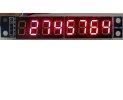
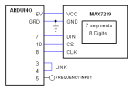
C code is for setting timer2 and timer0 to generate 1 second time base divided from the 16MHz crystal, timer1 is the counter. The 7 segment display MAX7219 is driven by software SPI, bit banging the 16 bits command to the display driver. The Arduino uno can count up to 6 MHz so digit 8 is not used. Leading zeros are blanked.
B4X:
Sub Process_Globals
    Public Serial1 As Serial
    Public DIN As Pin
    Public CLK As Pin
    Public CS As Pin
    Public out6 As Pin
    Public out9 As Pin
    Public out3 As Pin
    Public in4 As Pin
    Public in5 As Pin
    Public freq As UInt
    Public overf As Byte

End Sub


Private Sub AppStart
    Dim i As Byte
    Serial1.Initialize(9600)

    RunNative ("setTimers",Null)
    DIN.Initialize(7, DIN.MODE_OUTPUT)
    CLK.Initialize(8, CLK.MODE_OUTPUT)
    CS.Initialize(10, CS.MODE_OUTPUT)
    out6.Initialize(6, out6.MODE_OUTPUT)
    out9.Initialize(9, out9.MODE_OUTPUT)
    out3.Initialize(3, out3.MODE_OUTPUT)
    in4.Initialize(4, in4.MODE_INPUT)
    in5.Initialize(5, in5.MODE_INPUT)

    '7219 init
    cmnd(0x0b, 0x07)    'scan limit
    cmnd(0x09, 0xff)    'decode mode
    cmnd(0x0f, 0x00)    'no test
    cmnd(0x0a, 0x02)    'intensity (second byte) can be 0-15 (0x00-0x0F)
    cmnd(0x0c, 0x01)    'shutdown=on

    For i=1 To 8        'blank 8 digits
        cmnd(i, 0x0f)
    Next
    cmnd(4, 0x01)     'Hi
    cmnd(5, 0x0c)
    dly_us

    counter
End Sub

Private Sub counter
    Private freq2 As ULong
    Private i, d(8), nz As Byte

    Do While True
        Do While out6.DigitalRead=True
        Loop
        Do While out6.DigitalRead=False        'wait for start of 1 sec
        Loop
        overf=0
        RunNative ("count",Null)

        Do While out6.DigitalRead=True
            RunNative ("count2",Null)
        Loop

        RunNative ("count3",Null)

        freq2 = overf * 65536 + freq
        'Log(freq2)
        'convert to decimal
        For i=0 To 7
            d(i)=freq2 Mod 10
            freq2=freq2 / 10
        Next
        'remove leading zeros
        nz=1
        For i=8 To 2 Step -1
            If d(i-1)=0 And nz=1 Then
                cmnd(i, 0x0f)
            Else
                cmnd(i, d(i-1))
                nz=0
            End If
        Next
        cmnd(1, d(0))

    Loop
End Sub

    'address+data
Sub cmnd(addr As Byte, dataB As Byte)
    Dim b As Byte

    CS.DigitalWrite(False)
    For b=0 To 7
       If Bit.ShiftRight(addr,7-b) Mod 2 =1 Then
               DIN.DigitalWrite(True)
        Else
            DIN.digitalWrite(False)
        End If
       clock
    Next

    For b=0 To 6
        If Bit.ShiftRight(dataB ,7-b) Mod 2 = 1 Then
               DIN.DigitalWrite(True)
        Else
            DIN.DigitalWrite(False)
        End If
       clock
    Next
    If dataB Mod 2 = 1 Then DIN.DigitalWrite(True) Else DIN.digitalWrite(False)
    CLK.DigitalWrite(True)
    dly_us
    CS.DigitalWrite(True)
    dly_us
    CLK.DigitalWrite(False)
    dly_us
End Sub

Sub clock
    CLK.DigitalWrite(True)
  dly_us
    CLK.DigitalWrite(False)
  dly_us
End Sub

Sub dly_us    'set clk frequency to about 100KHz
    Dim j As Byte
  For j=0 To 2
    j=j
  Next
End Sub

#if C
void setTimers(B4R::Object* o)
{
          //set timer0 in=250Hz out=1Hz
    OCR0A = 249;
    TCCR0A=0b1000011;
    TCCR0B=0b1110;  //  PWM mode, input T0 pin D4

      // set timer2 in=16MHz out=250Hz
    OCR2A =249;
    OCR2B = 125;
    TCCR2A=0b110011;  //output B in phase, fast PWM mode
    TCCR2B=0b1110; // set prescaler to 256 and start the timer

        //  set timer1
    OCR1A = 32767;   //32768 counts
    TCCR1A = 0b1000011;
    TCCR1B = 0b11110; //input pin D5
}

void count(B4R::Object* o)
{
    TIFR1 |= _BV(1);    //reset interrupt
    OCR1A = 65535;  //32767
    TCNT1=0;

}

void count2(B4R::Object* o){

  if(TIFR1 & _BV(1)) {(b4r_main::_overf)=(b4r_main::_overf)+1; TIFR1 |= _BV(1);}
 }

void count3(B4R::Object* o){

   (b4r_main::_freq) = TCNT1 ;
}
#End if