B4J Library [IoT] jPi4J - Raspberry Pi GPIO controller

Updated libraries: https://www.b4x.com/android/forum/threads/pi4j2-raspberry-pi-i-o-library.136113/#content

This is a wrapper for Pi4J library.
It allows you are control the Raspberry Pi board GPIO pins.

Using this library is quite simple. You can use it from a UI app or non-UI app.

First you should initialize a GpioController object.
The second step is to initialize one or more pins.

You can provision each pin to be an input pin or output pin. Input pins allow you to listen for state changes. Output pins allow you to set their state.

The following program initializes two pins. Pin1 is an input pin and pin2 is an output pin. Pin2 state is changed every 5 seconds with a timer:
B4X:
'Non-UI application (console application)
#Region  Project Attributes
   #CommandLineArgs:
   #MergeLibraries: true
#End Region

Sub Process_Globals
   Private controller As GpioController
   Private Pin2 As GpioPinDigitalInput
   Private Pin1 As GpioPinDigitalOutput
   Private Timer1 As Timer
End Sub

Sub AppStart (Args() As String)
   controller.Initialize
   Pin1.Initialize(1, True) 'GpioPinDigitalOutput
   Pin2.Initialize("Pin2", 2) 'GpioPinDigitalInput
   Pin2.SetPinPullResistance("PULL_DOWN")

   Log("Monitoring Pin2 state")
   Timer1.Initialize("Timer1", 5000)
   Timer1.Enabled = True
   StartMessageLoop
End Sub

Sub Timer1_Tick
   Pin1.State = Not(Pin1.State)
   Log("Switching Pin1 state. Pin1 state = " & Pin1.State)
End Sub

Sub Pin2_StateChange(State As Boolean)
   Log("Pin2 StateChange event: " & State)
End Sub

The pins scheme is available here: http://pi4j.com/usage.html

The output of this program:
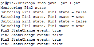
SS-2014-02-05_14.09.17.png


B4J-Bridge is very useful when working with this board: http://www.b4x.com/android/forum/threads/remote-debugging-with-b4j-bridge.38804/
You can download it to the board with this command:
B4X:
wget https://www.b4x.com/b4j/files/b4j-bridge.jar
Then run it as root:
B4X:
sudo <path to java> -jar b4j-bridge.jar

SS-2014-03-25_12.42.39.png


PiFace extension

V1.00 adds support for the PiFace extension: http://www.savagehomeautomation.com/piface


See this post: http://www.b4x.com/android/forum/threads/jpi4j-raspberry-pi-gpio-controller.37493/#post-232767

Download link: www.b4x.com/b4j/files/jPi4J.zip
 
Last edited:

MbedAndroid

Well-Known Member
Licensed User
Longtime User
it was connected....
but i will retry as i used SSH. Will try it directly and let you know
 

MbedAndroid

Well-Known Member
Licensed User
Longtime User
your're right erel :(
with sudo java -jar b4j-bridge.jar it works...
thanks !
i think i missed the "connected" message
 

KMatle

Expert
Licensed User
Longtime User
The RB has 8 digital inputs. With them we can check 8 switches (or even more with more boards).

8 Bits represent 255 different values. For sure there is some hw to convert it but I don't know the word for it. Can someone help?

My idea is to handle up to 255 switches with the 8 inputs.
 

Roycefer

Well-Known Member
Licensed User
Longtime User
I think you're looking for a multiplexer. This will use up some of your digital outputs, as well.
 

Cableguy

Expert
Licensed User
Longtime User
Search for multiplexer circuits/ ICs. as roycefer stated, some digital pins will be needed to control wich input to use.
for example, a 1 to 16 mux uses 5 digital pins, 4 to select witch of the 16 inputs will be selected.
So for 256 digital I/O you will need 8 control pins and another to retrieve the value.

There may be other ways like cascading Muxes...

You can also check non-traditional multiplexing techniques, like charlieplexing
 
Last edited:

KMatle

Expert
Licensed User
Longtime User
Trying to run a 2x16 LCD display over my piFace 2 (via digital outputs). It has a serial in.

I use these pins:

PinFunction
1Ground
2Positive 5 volt
3VEE (Connect to +5 and GND through 10k Pot for display contrast)
4RS (Low for command - high for characters)
5RW (Low for write - high for read)
6E (Toggle to load data and command)
7-14Data pins
15Backlight +
16Backlight Ground

As I've understood by setting #6 from low to high and back the data is writen to the display.

I try it with this code by setting the outputs:

B4X:
Select seq
        Case 1
            e.State=True
            seq=seq+1
        Case 2
            d4.State=True
            d5.State=True
            d6.State=False
            d7.State=False
            rs.State=False
            rw.State=False
            seq=seq+1
        Case 3
            e.State=False
            seq=seq+1
        Case 4
            e.State=True
            seq=seq+1
        Case 5
            d4.State=True
            d5.State=True
            d6.State=False
            d7.State=False
            rs.State=False
            rw.State=False
            seq=seq+1
        Case 6
            e.State=False
            seq=seq+1
        Case 7
            e.State=True
            seq=seq+1
        Case 8
            d4.State=False
            d5.State=True
            d6.State=False
            d7.State=True
            rs.State=False
            rw.State=False
            seq=seq+1

The code is crap but I wanted to try it. It's called by a timer (0,5secs). Am I totally wrong here or is it the right direction?
 

Mark Turney

Active Member
Licensed User
Longtime User
If no one else beats me to it, I'll try the same setup tomorrow and let you know what I get.
 

Mark Turney

Active Member
Licensed User
Longtime User
I just had a chance to solder wires to my 2x16 LCD. Will experiment a bit tonight and tomorrow.
 

Mark Turney

Active Member
Licensed User
Longtime User
I just realized that I'm not sure what you're trying to display, but I at least got mine to come on. Haven't soldered in quite a while ... forgot how good the fumes smell. LOL o_O ...

Can you post the full code? If you don't want it public, just send me a private message and I will test for you. Thanks!
IMG_3291.JPG
 

KMatle

Expert
Licensed User
Longtime User
I just realized that I'm not sure what you're trying to display, but I at least got mine to come on. Haven't soldered in quite a while ... forgot how good the fumes smell. LOL o_O ...

Can you post the full code? If you don't want it public, just send me a private message and I will test for you. Thanks!
View attachment 38788

See here: https://www.b4x.com/android/forum/threads/solved-iot-raspberry-wiringpi-b4j-lcd-2x16.60252/

It's all about the mapping. Take a look to the table (GPIO2 is not always PIN2). The working code is included.

PS: Your display isn't conncected (except power) :D:D Maybe this will not work...
 

Mark Turney

Active Member
Licensed User
Longtime User
Ha ha ha on the "connections" comment .... for just a split second, I was going to clarify the pic until I realized that you were kidding ;)....
 

HARRY

Active Member
Licensed User
Longtime User
Hi,

I am starting a project to communicate from my Raspberry with a I2c device. Starting point is the example by Erel in one of the posts in this thread. I think I am doing something totally wrong, but do not know what. I am not familiar with java objects. The program, up to now looks like

B4X:
'Non-UI application (console / server application)
#Region  Project Attributes
    #CommandLineArgs:
    #MergeLibraries: True
#End Region

Sub AppStart (Args() As String)
   
End Sub


Sub Process_Globals
    Dim bus As JavaObject = GetBus(1)
    Dim device As JavaObject = GetDevice(bus, 0)
End Sub

'Bus methods
Sub GetBus(BusNumber As Int) As JavaObject
   Dim factory As JavaObject
   Return factory.InitializeStatic("com.pi4j.io.i2c.I2CFactory").RunMethodJO("getInstance", Array As Object(BusNumber))
End Sub

Sub GetDevice(bus As JavaObject, Address As Int) As JavaObject
   Return bus.RunMethodJO("getDevice", Array As Object(Address))
End Sub

Sub CloseBus (bus As JavaObject)
   bus.RunMethod("close", Null)
End Sub

'Device methods
Sub Read(device As JavaObject) As Int
   Return device.RunMethod("read", Null)
End Sub

Sub Read2 (device As JavaObject, Buffer() As Byte, Offset As Int, Size As Int) As Int
   Return device.RunMethod("read", Array As Object(Buffer, Offset, Size))
End Sub

Sub Write(device As JavaObject, b As Byte)
   device.RunMethod("write", Array As Object(b))
End Sub

Sub Write2(device As JavaObject, Buffer() As Byte, Offset As Int, Size As Int)
   device.RunMethod("write", Array As Object(Buffer, Offset, Size))
End Sub

When I do Compile and Run, I get a message:
B4J version: 3.70 BETA 1
Parsing code. Error
Error parsing program.
Error description: Parameter name cannot hide global variable name.
Occurred on line: 27 (Main)
Sub CloseBus (bus As JavaObject)

and in the log:
7* Parameter name cannot hide global variable name "
and the text 'unused variable name 'device'

What am i doing wrong?

Harry
 

Roycefer

Well-Known Member
Licensed User
Longtime User
You have global variables called "device" and "bus" and you also have parameters for subs called "device" and "bus". This isn't permitted. Either change the name of the global variables or change the name of the parameters.
 
Top