B4J Library [IoT] jPi4J - Raspberry Pi GPIO controller

Updated libraries: https://www.b4x.com/android/forum/threads/pi4j2-raspberry-pi-i-o-library.136113/#content

This is a wrapper for Pi4J library.
It allows you are control the Raspberry Pi board GPIO pins.

Using this library is quite simple. You can use it from a UI app or non-UI app.

First you should initialize a GpioController object.
The second step is to initialize one or more pins.

You can provision each pin to be an input pin or output pin. Input pins allow you to listen for state changes. Output pins allow you to set their state.

The following program initializes two pins. Pin1 is an input pin and pin2 is an output pin. Pin2 state is changed every 5 seconds with a timer:
B4X:
'Non-UI application (console application)
#Region  Project Attributes
   #CommandLineArgs:
   #MergeLibraries: true
#End Region

Sub Process_Globals
   Private controller As GpioController
   Private Pin2 As GpioPinDigitalInput
   Private Pin1 As GpioPinDigitalOutput
   Private Timer1 As Timer
End Sub

Sub AppStart (Args() As String)
   controller.Initialize
   Pin1.Initialize(1, True) 'GpioPinDigitalOutput
   Pin2.Initialize("Pin2", 2) 'GpioPinDigitalInput
   Pin2.SetPinPullResistance("PULL_DOWN")

   Log("Monitoring Pin2 state")
   Timer1.Initialize("Timer1", 5000)
   Timer1.Enabled = True
   StartMessageLoop
End Sub

Sub Timer1_Tick
   Pin1.State = Not(Pin1.State)
   Log("Switching Pin1 state. Pin1 state = " & Pin1.State)
End Sub

Sub Pin2_StateChange(State As Boolean)
   Log("Pin2 StateChange event: " & State)
End Sub

The pins scheme is available here: http://pi4j.com/usage.html

The output of this program:
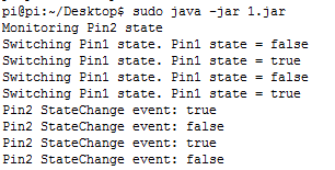
SS-2014-02-05_14.09.17.png


B4J-Bridge is very useful when working with this board: http://www.b4x.com/android/forum/threads/remote-debugging-with-b4j-bridge.38804/
You can download it to the board with this command:
B4X:
wget https://www.b4x.com/b4j/files/b4j-bridge.jar
Then run it as root:
B4X:
sudo <path to java> -jar b4j-bridge.jar

SS-2014-03-25_12.42.39.png


PiFace extension

V1.00 adds support for the PiFace extension: http://www.savagehomeautomation.com/piface


See this post: http://www.b4x.com/android/forum/threads/jpi4j-raspberry-pi-gpio-controller.37493/#post-232767

Download link: www.b4x.com/b4j/files/jPi4J.zip
 
Last edited:

Michael1968

Active Member
Licensed User
Longtime User
It should be simple to call this API with JavaObject.

B4X:
Dim lcd As JavaObject
lcd.InitializeStatic("com.pi4j.wiringpi.Lcd")
Dim handle as Int = lcd.RunMethod("lcdInit", Array(<all the ints go here>))
lcd.RunMethod("lcdPuts", Array(handle, "text"))

thx Erel ....it works now ;)
 

StarinschiAndrei

Active Member
Licensed User
Longtime User
Hi Erel,
I try to reproduce your example on my rpi but there is no changes on pin2 when i press the button.Could you please tell me what's wrong ?
upload_2014-8-29_18-43-17.png

B4X:
'Non-UI application (console / server application)
#Region  Project Attributes
    #CommandLineArgs:
    #MergeLibraries: True
#End Region

Sub Process_Globals
Private controller As GpioController
  Private pin2 As GpioPinDigitalInput
  Private pin1 As GpioPinDigitalOutput
  Private Timer1 As Timer

End Sub

Sub AppStart (Args() As String)
    controller.Initialize
  pin1.Initialize(1, True) 'GpioPinDigitalOutput
  pin2.Initialize("Pin2", 2) 'GpioPinDigitalInput
  pin2.SetPinPullResistance("PULL_DOWN")

  Log("Monitoring Pin2 state")
  Timer1.Initialize("Timer1", 5000)
  Timer1.Enabled = True
  StartMessageLoop
End Sub
Sub Timer1_Tick
  pin1.State = Not(pin1.State)
  Log("Switching Pin1 state. Pin1 state = " & pin1.State)
End Sub

Sub Pin2_StateChange(State As Boolean)
  Log("Pin2 StateChange event: " & State)
End Sub
upload_2014-8-29_18-47-18.png
 

Toley

Active Member
Licensed User
Longtime User
Sub Timer1_Tick
pin1.State = Not(pin1.State)Log("Switching Pin1 state. Pin1 state = " & pin1.State)End Sub

It looks like the change is on pin1
 

StarinschiAndrei

Active Member
Licensed User
Longtime User
The timer updates pin1 state every 5 seconds.

In my tests I short-circuited pin2 to change its state.
Thank you Erel, it was my fault. Below the right circuit
upload_2014-9-1_20-29-52.png

and the code :
B4X:
Sub Process_Globals
Private controller As GpioController
  Private pin2 As GpioPinDigitalInput
  Private pin1 As GpioPinDigitalOutput
  Private Timer1 As Timer
  Private ms As Long
End Sub

Sub AppStart (Args() As String)
    controller.Initialize
  pin1.Initialize(1, True) 'GpioPinDigitalOutput
  pin2.Initialize("Pin2", 2) 'GpioPinDigitalInput
  pin2.SetPinPullResistance("PULL_DOWN")
  ms =1000
  Log("Monitoring Pin2 state")
  Timer1.Initialize("Timer1", ms)
  Timer1.Enabled = True
  StartMessageLoop
End Sub
Sub Timer1_Tick
  pin1.State = Not(pin1.State)
  Log("Switching Pin1 state. Pin1 state = " & pin1.State & "Interval :" & ms )
End Sub

Sub Pin2_StateChange(State As Boolean)
If State = False Then
    If ms <9000 Then
          Log("Pin2 StateChange event: " & State)
          ms =ms+ 1000
    Else
          ms =1000
    End If   
   Timer1.Initialize("Timer1",ms)
End If
End Sub
 
Last edited:

StarinschiAndrei

Active Member
Licensed User
Longtime User
Than
I've uploaded a new beta version that allows you to provision an analog input pin. I haven't tested this functionality.

Initialize a GpioPinAnalogInput object and then read the value with pin.Value. You should use a timer to periodically read the value.
Thank you,
 

StarinschiAndrei

Active Member
Licensed User
Longtime User
Than

Thank you,

Hi Erel,
I try the new version :( with different pins (1,4 and the last was 16) below the code and the error message
B4X:
Sub Process_Globals
Private controller As GpioController
  Private pin16 As GpioPinAnalogInput

  'Private pin1 As GpioPinDigitalOutput
Private timer1 As Timer
End Sub

Sub AppStart (Args() As String)
    controller.Initialize
pin16.Initialize(16)
  Log("Monitoring Pin2 state")
    timer1.Initialize("Timer1", 1000)
      timer1.Enabled = True
  StartMessageLoop
End Sub
Sub timer1_tick
    Log(pin16.Value)
End Sub
upload_2014-9-12_20-24-33.png
 

woniol

Active Member
Licensed User
Longtime User
I haven't tried this yet, but the RPi pins are all digital. To use analog input you will probably need another circuit with an interface to the Pi.
 

woniol

Active Member
Licensed User
Longtime User
LM35 is not similar to DS18b20.
LM35 is analog temperature sensor - it gives analog output
DS18b20 is digital temperature sensor - is uses 1wire bus for data output.

1wire is not yet supported by pi4j

Plese have a look at DS1621 - it uses i2c bus supported by pi4j.
 
Last edited:

StarinschiAndrei

Active Member
Licensed User
Longtime User
LM35 is not similar to DS18b20.
LM35 is analog temperature sensor - it gives analog output
DS18b20 is digital temperature sensor - is uses 1wire bus for data output.

1wire is not yet supported by pi4j

Plese have a look at DS1621 - it uses i2c bus supported by pi4j.
Yes , you are right. I found this how to read analog sensor, i didn't tested but sounds good.
https://learn.adafruit.com/basic-resistor-sensor-reading-on-raspberry-pi/overview
probably i will buy MCP3008 chip this is the easiest solution
 

woniol

Active Member
Licensed User
Longtime User
I will try to find some time this weekend and write a class for DS1621 with pi4j.
 

Michael1968

Active Member
Licensed User
Longtime User
LM35 is not similar to DS18b20.
LM35 is analog temperature sensor - it gives analog output
DS18b20 is digital temperature sensor - is uses 1wire bus for data output.

1wire is not yet supported by pi4j

Plese have a look at DS1621 - it uses i2c bus supported by pi4j.

Hi Woniol
to use DS18b20 it's very easy

Load the Kernel Modul:
$sudo modprobe w1-gpio
$sudo modprobe w1-therm

this creates a folder:
/sys/bus/w1/devices/10-00080293bd31
10-00080293bd31 is the rom-ID of the DS18b20

in this folder there is a file named w1_slave with the temperature

I read the file with textreader line by line to get the temperature
it works perfect for me

Best regards
Michael
 
Top